Scaffolding & Shoring
The components behind temporary works.
Scaffolds, props, falsework towers and trench shoring all carry people or concrete for a time, then come down. GV supplies the steel components inside five of these systems: cuplock scaffold, working decks, adjustable props, shoring towers and trench struts. We source each part to the size series and standard your project requires. These sections show how the parts work together.
SCAFFOLDING & SHORING SYSTEMS
How the components work together.
Below are five scaffolding and shoring systems and the components GV supplies in each, with what every part does once the system is up.
SCAFFOLDING & SHORING SYSTEMS
Five systems these parts build.
Each section explains how the components work together and names the GV products used.
CUPLOCK
Cuplock system scaffold
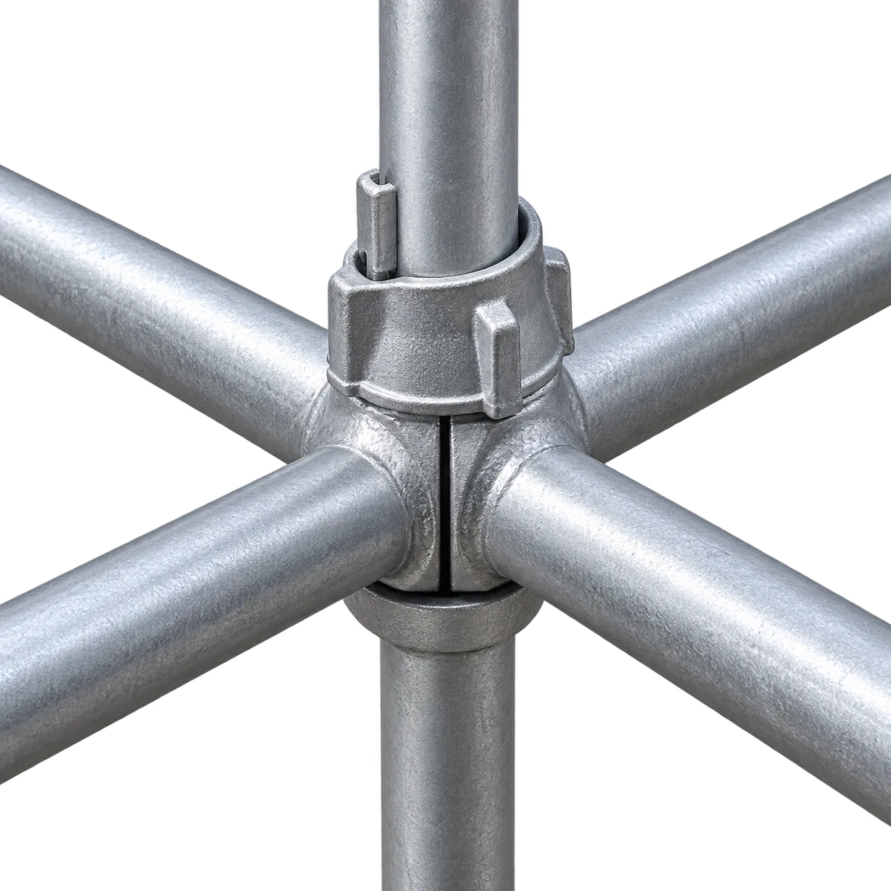
Cuplock is a system scaffold used for facades, birdcages, tank and plant access, and stair towers on construction projects. Its standards carry cups every 0.5 m, and each node takes up to four horizontals with no loose fittings, so a crew can erect regular bays of 0.6 to 3.0 m quickly. Buyers specify the tube, the component lengths and the finish to their project requirements.
Cuplock System supplies the standards, ledgers and transoms: the ledger blades sit in the bottom cup and the top cup is turned down over them to lock the joint. Screw Jack with Base Plate & Wing Nut levels each standard at the foot, and Planks form the deck at every working lift. Ties, guardrail boards and fittings come from the scaffold contractor.
Products in this system
Cuplock System
Diameter: 2 in (N.B.) / 48.3 mm (O.D.), 3.2 or 4.0 mm wall · Length: 3-12 ft / 1-4 m; verticals in 0.5 m steps
Specifications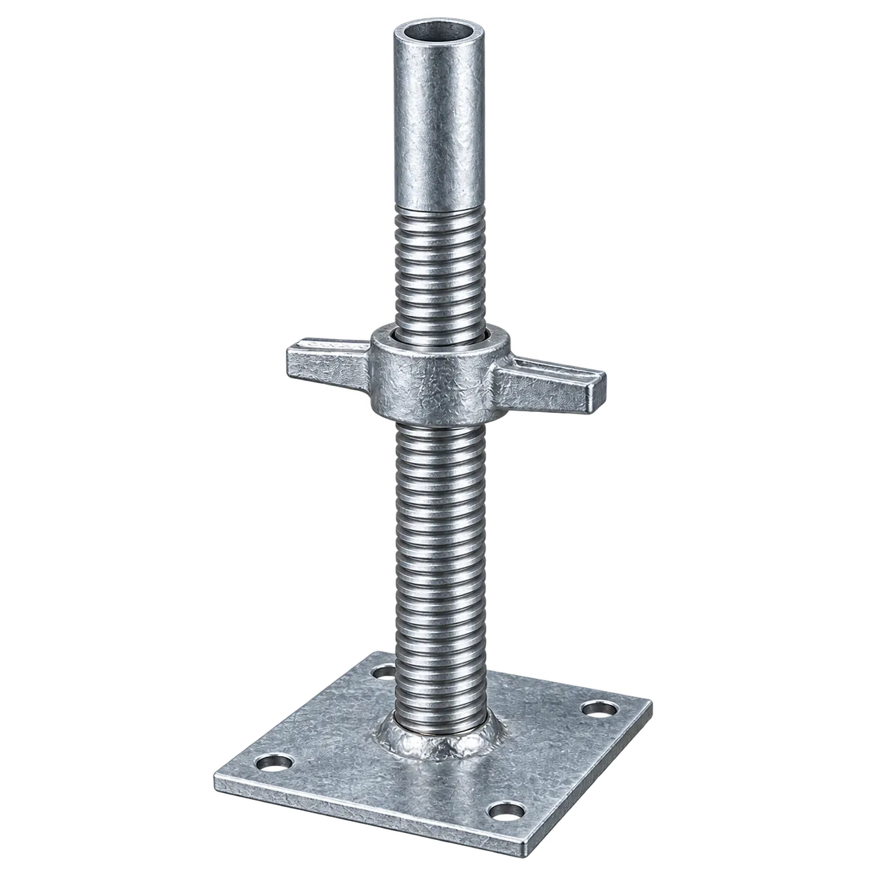
Screw Jack with Base Plate & Wing Nut
Diameter: 1-1/4, 1-1/2 in (N.B.) / 33.7, 38, 38.1 mm (O.D.); 26-48 mm to order · Length: 24-36 in / 600-900 mm
Specifications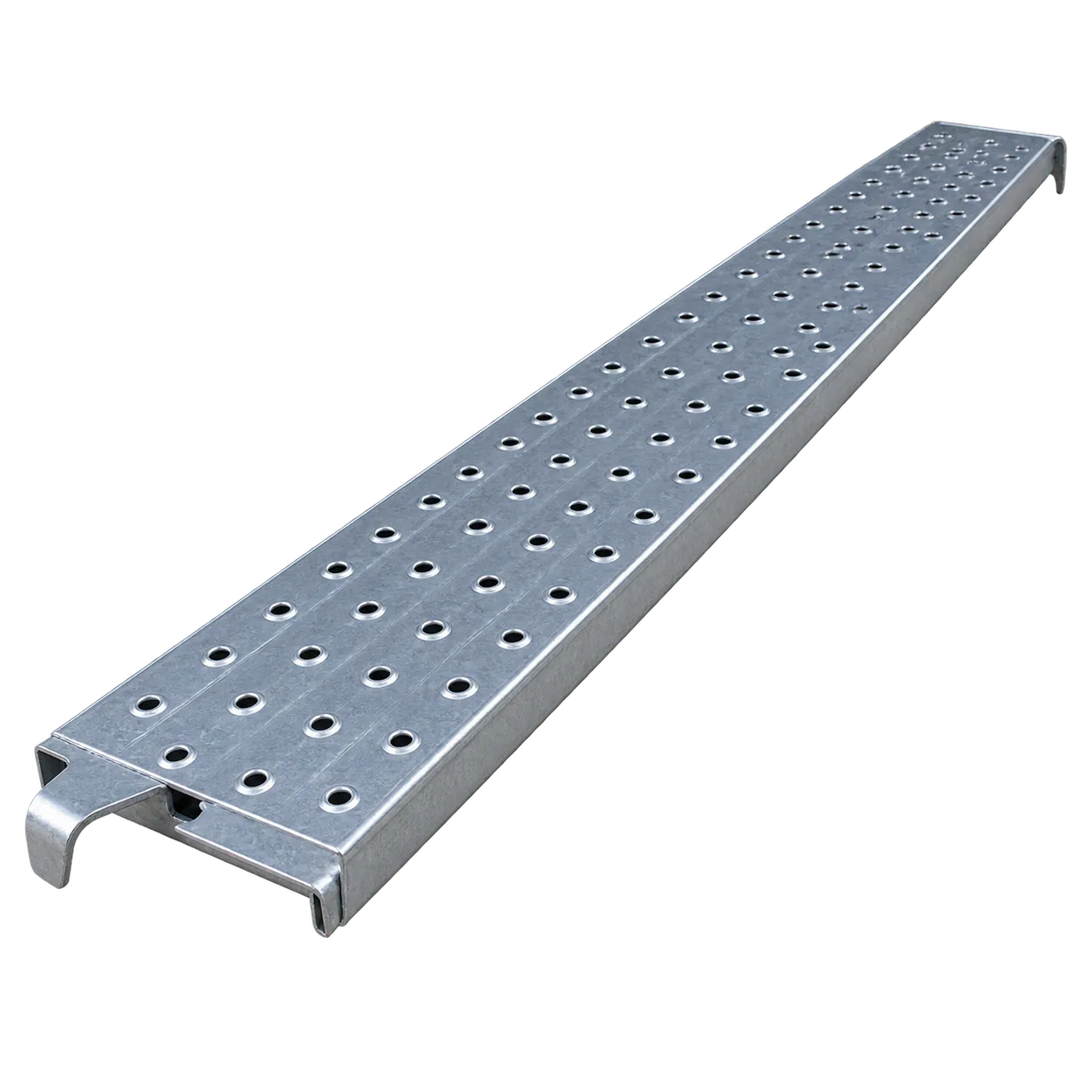
Planks
Width: 9, 10, 12 in / 200-500 mm; 225, 230, 238, 250, 300, 320 mm common · Depth: 38, 50, 57, 63, 76 mm
SpecificationsWORKING DECKS
Working platforms and decks
Every scaffold lift where people work needs a full, flat deck. On system scaffolds the boards hook over the ledgers or transoms; on tube-and-fitting scaffolds plain-ended boards rest on transoms clipped to the tube. US buyers typically specify planks under OSHA 1926.451 dimensions.
Planks are the deck itself, pressed from steel strip and perforated so water drains and the surface grips underfoot, with hook ends or plain ends to suit the scaffold. Screw Jack with Base Plate & Wing Nut levels the scaffold so each deck sits true.
Products in this system
Planks
Width: 9, 10, 12 in / 200-500 mm; 225, 230, 238, 250, 300, 320 mm common · Depth: 38, 50, 57, 63, 76 mm
SpecificationsScrew Jack with Base Plate & Wing Nut
Diameter: 1-1/4, 1-1/2 in (N.B.) / 33.7, 38, 38.1 mm (O.D.); 26-48 mm to order · Length: 24-36 in / 600-900 mm
SpecificationsPROPS
Adjustable steel props
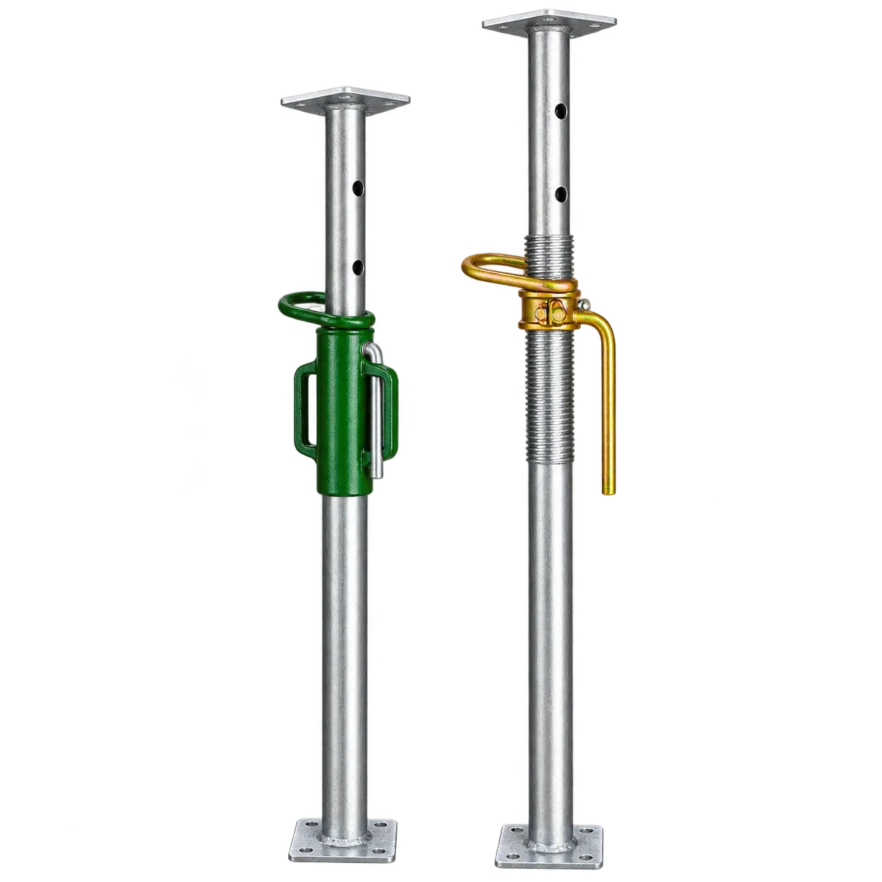
The adjustable steel prop is the standard temporary support under slab formwork, beams, lintels and openings, and for back-propping floors below a new pour. A standard series sizes props 0 to 4, each covering a band of heights.
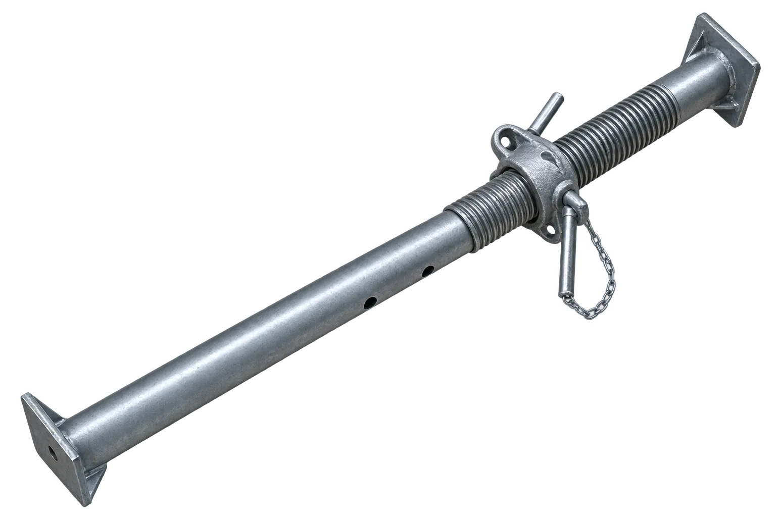
GV supplies props complete: the inner tube slides inside the Threaded Tube, the G Pin passes through the inner tube and rests on the Prop Nut to set the coarse height, and turning the Prop Nut on the thread brings the prop to its final height. We also supply each part on its own to keep hire fleets in service and ready for the next job.
Products in this system
Props
Size: #0, #1, #2, #3, #4 · Height: #0: 1.1-1.8 m; #1: 1.75-3.12 m; #2: 2.0-3.4 m; #3: 2.59-3.96 m; #4: 3.2-4.87 m
Specifications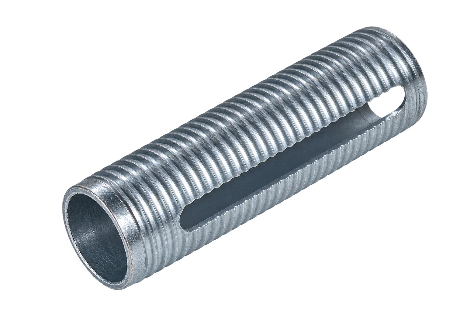
Threaded Tube
Size: #0, #1, #2, #3, #4 · Tube: 60.3 mm O.D., 3.6 mm wall
Specifications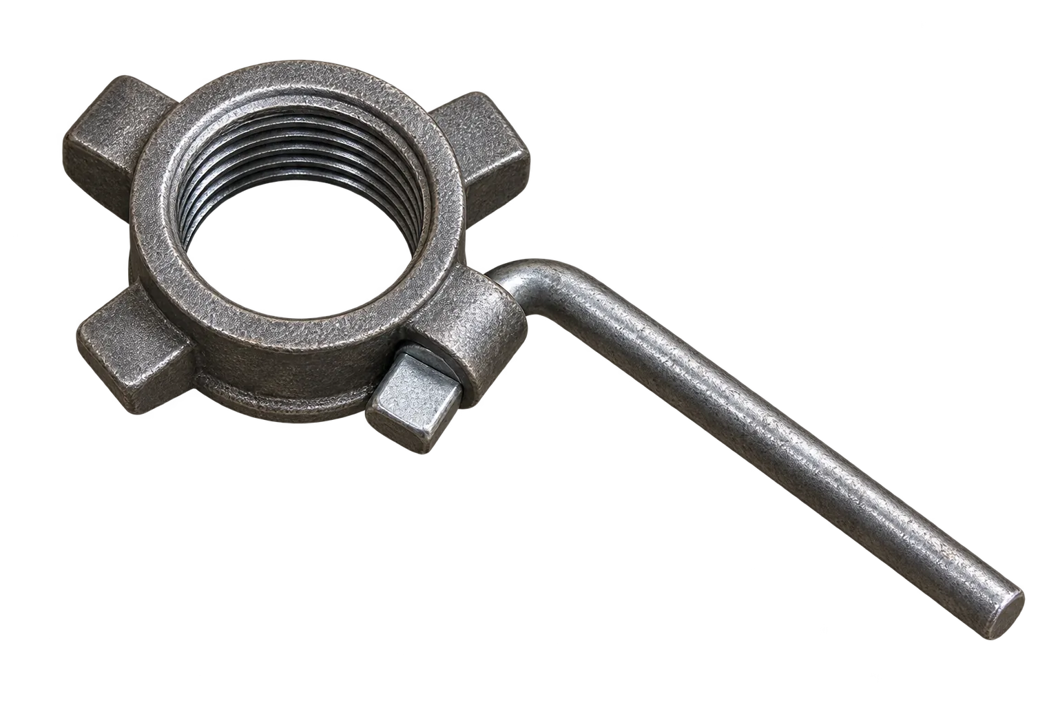
Prop Nut
Size: #0, #1, #2, #3, #4 · Thread: 4 TPI, to suit 60.3 mm threaded tubes
Specifications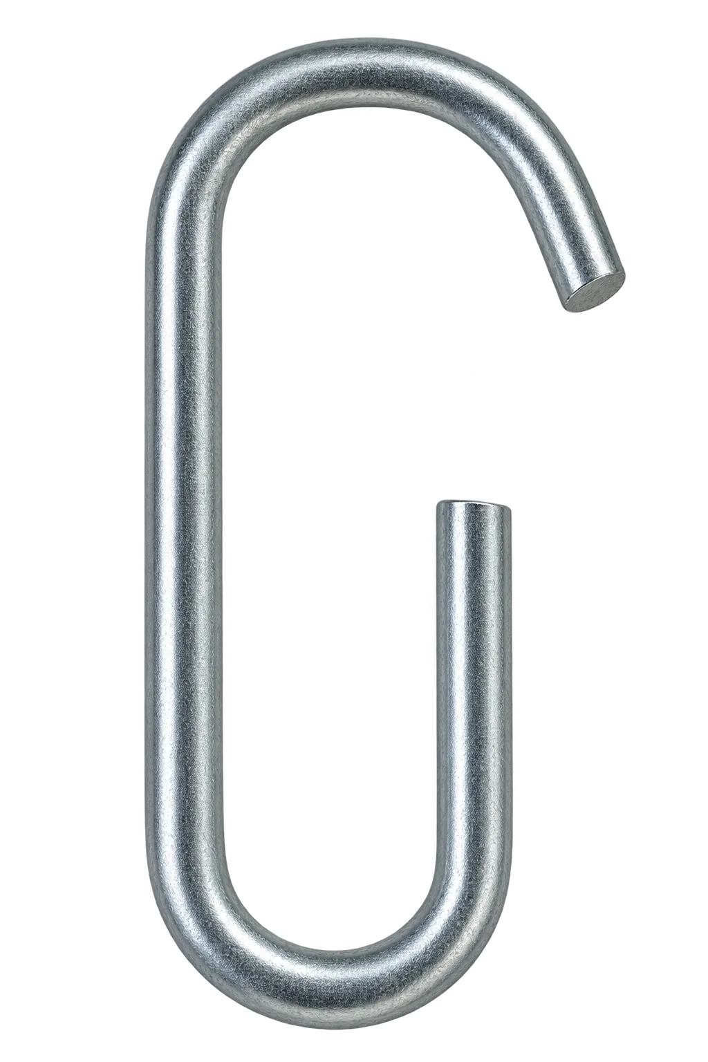
G Pin
Size: #0, #1, #2, #3, #4 · Diameter: 10-18 mm
SpecificationsFALSEWORK
Falsework and shoring towers
When formwork is too high or too heavily loaded for single props, falsework towers carry it instead: bridge decks, transfer slabs, deep beams and tall halls. Each tower stands on adjustable jacks and carries primary beams in U-heads or fork heads at the top.
Hi-Load Screw Jack with Wing Nut sits at the head of each leg, holding the beam in its U-head and setting the final level. Screw Jack with Base Plate & Wing Nut stands each leg on the ground, and Cuplock System can form the tower frame itself. Beams and formwork come from the formwork contractor.
Products in this system
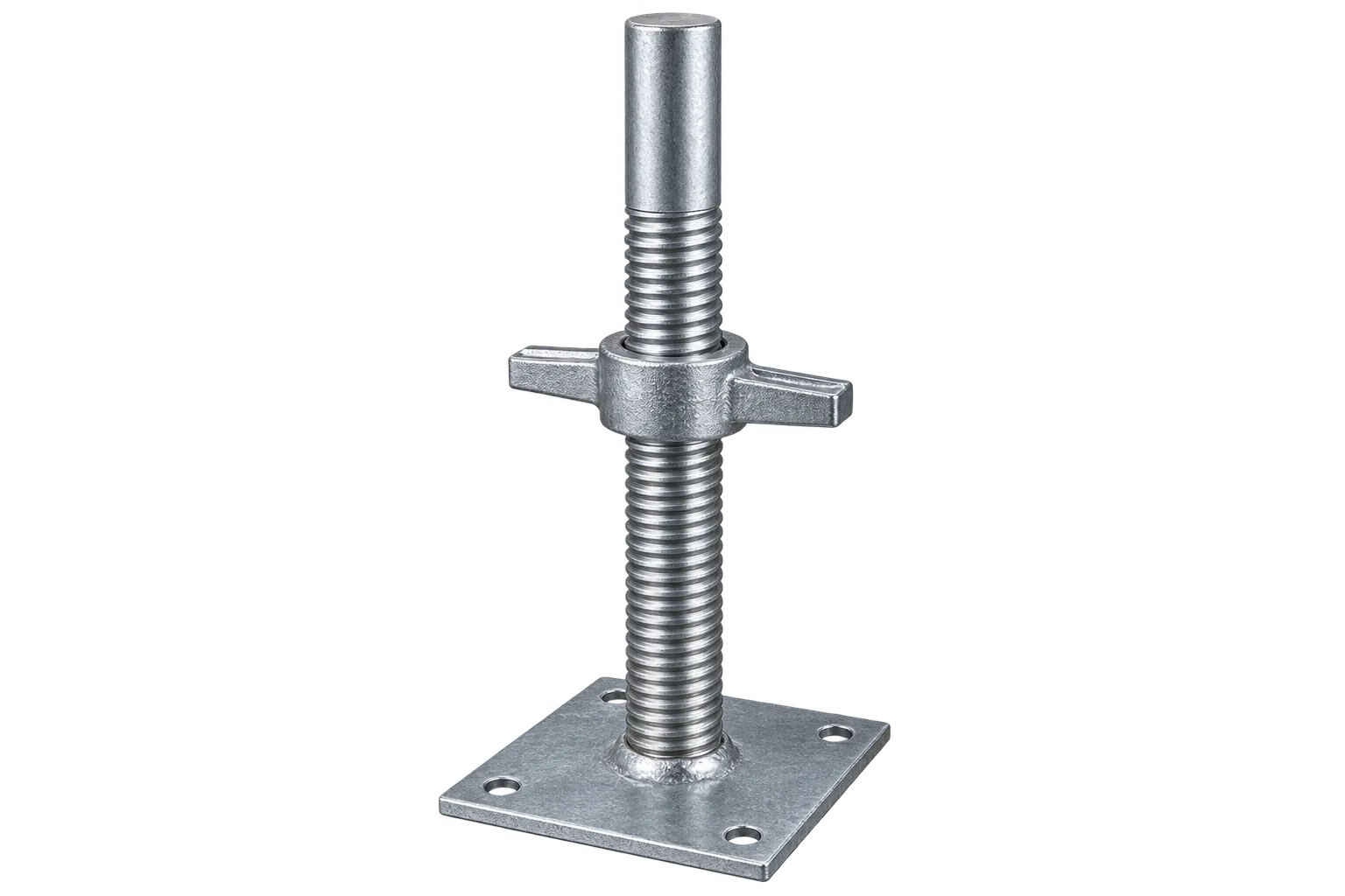
Hi-Load Screw Jack with Wing Nut
Diameter: 1-1/4, 1-1/2 in (N.B.) / 48.3, 60.3 mm (O.D.) · Length: 30-120 in / 760 mm-3 m
SpecificationsScrew Jack with Base Plate & Wing Nut
Diameter: 1-1/4, 1-1/2 in (N.B.) / 33.7, 38, 38.1 mm (O.D.); 26-48 mm to order · Length: 24-36 in / 600-900 mm
SpecificationsCuplock System
Diameter: 2 in (N.B.) / 48.3 mm (O.D.), 3.2 or 4.0 mm wall · Length: 3-12 ft / 1-4 m; verticals in 0.5 m steps
SpecificationsTRENCH SHORING
Trench shoring with struts
Trenches for drainage, water and cable runs need their sides held back while people work below ground level. Trench sheets or timbers line each face, walings run along them, and struts set across the excavation hold the two sides apart. US contractors reference OSHA 1926 Subpart P for the shoring design.
Trench Struts come in the same 0 to 4 size numbering as props. Each is extended to the trench width, pinned, then tightened on its screw so the claw end plates bite into the walings or sheets. The G Pin sets the strut's length; trench sheets and walings come from the groundworks contractor.